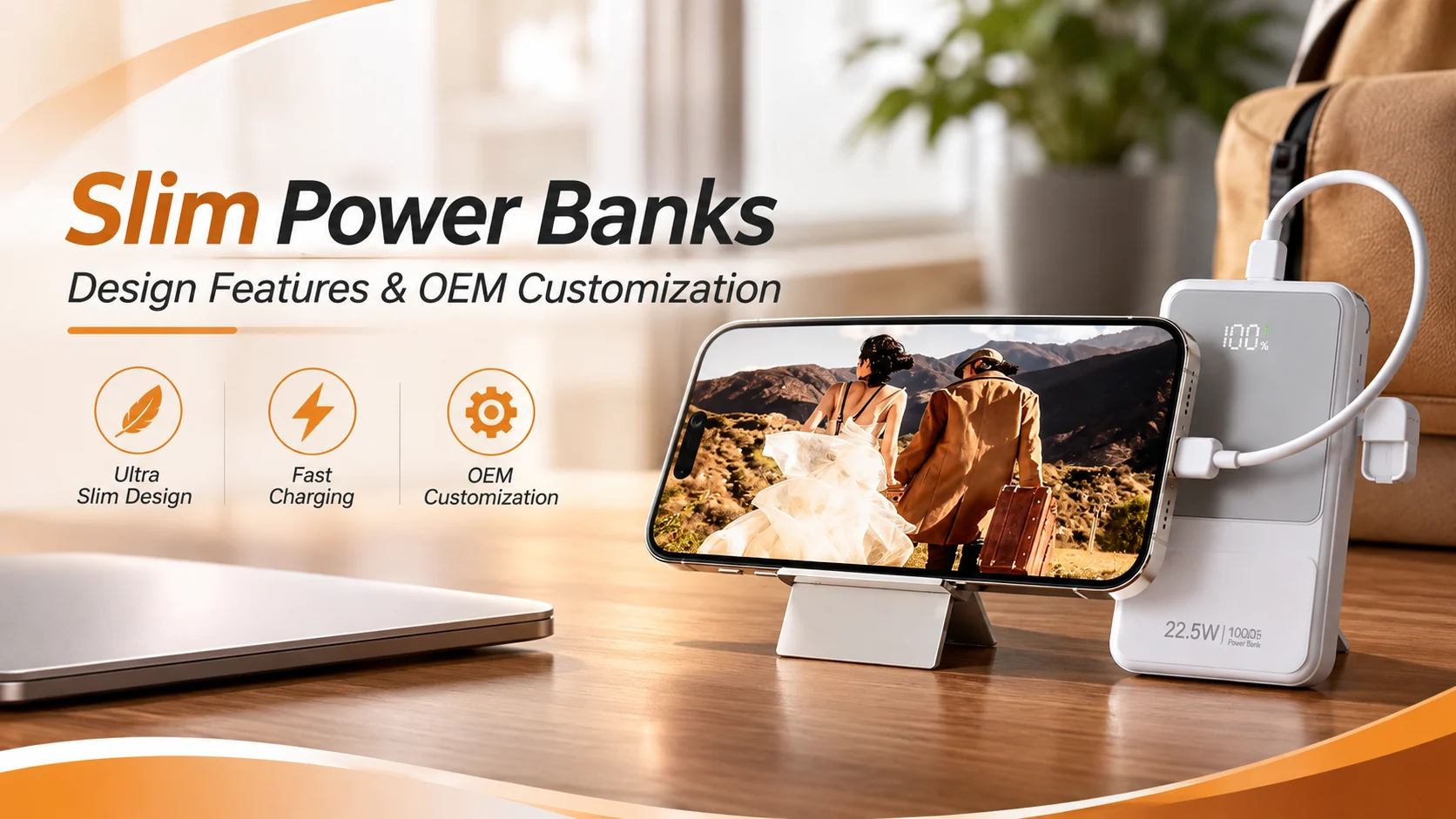
Slim power banks have become popular among consumers who prefer lightweight, compact, and easy-to-carry charging accessories. Their card-style appearance fits modern lifestyles, including business travel, daily commuting, and mobile device use.
For brands and OEM buyers, however, creating an ultra-slim portable charger involves more than reducing the enclosure thickness. A thinner body leaves less space for battery cells, circuit boards, insulation, and thermal management. Poor design decisions can affect battery expansion allowance, drop protection, structural strength, and operating temperature.
A successful slim power bank design must balance appearance, battery performance, mechanical protection, and manufacturing feasibility. This guide explores the main engineering considerations and OEM customization options for brands developing compact portable chargers.
1. The Appeal of Ultra-Slim Design in Modern Consumer Electronics
Slim portable chargers appeal to consumers who want convenient backup power without carrying bulky accessories. Their compact form also creates opportunities for product differentiation in retail, corporate gifting, and lifestyle electronics.
1.1 Why Consumers Prefer Slim Power Banks
Traditional power banks often use thick rectangular housings. Although these designs can accommodate larger batteries, they may feel bulky in pockets and small bags.
Ultra-slim designs offer several practical advantages:
- Easier storage in handbags, backpacks, and laptop sleeves.
- A lightweight feel for daily commuting.
- A clean appearance that complements modern smartphones.
- Convenient storage alongside business accessories.
- More flexibility for branded promotional products.
Card-style power banks are especially suitable for brands targeting consumers who value portability and minimalistic design.
However, a slim appearance should not come at the expense of usable capacity, charging performance, or product safety.
1.2 Common Slim Power Bank Design Styles
Different enclosure designs support different market positions.
| Design style | Main characteristics | Potential target market |
|---|---|---|
| Card-style | Flat profile and compact footprint | Everyday users and promotional gifts |
| Ultra-thin rectangular | Minimal thickness with a simple outline | Business travelers and lifestyle brands |
| Magnetic slim design | Designed for compatible magnetic phone attachment | Smartphone accessory brands |
| Compact curved design | Rounded edges and ergonomic surfaces | Fashion-oriented consumer electronics |
| Customized slim enclosure | Brand-specific dimensions, colors, and finishes | OEM and private-label products |
The ideal shape depends on battery dimensions, electronic components, assembly requirements, and target retail positioning.
1.3 Balancing Thickness, Capacity, and Portability
One of the biggest challenges in slim power bank development is balancing physical size with battery capacity.
Battery capacity is commonly measured in milliampere-hours (mAh). However, mAh alone does not describe the complete energy capacity of a power bank.
Watt-hours (Wh) provide a more useful comparison because they account for battery voltage.
The basic relationship is:
Energy (Wh) = Capacity (Ah) × Nominal Voltage (V)
For example, a 5,000mAh battery at a nominal voltage of 3.7V stores approximately 18.5Wh.
A higher-capacity battery generally requires more physical volume or a different cell configuration. Therefore, buyers should define their priorities early:
- Minimum capacity.
- Maximum thickness.
- Maximum product weight.
- Required output power.
- Number of output ports.
- Intended charging scenarios.
A realistic design brief helps engineers determine whether the proposed size and performance targets can work together.
2. Polymer Lithium Cells: The Core Engine Behind Slim Designs
Battery selection plays a major role in the development of slim power banks.
Lithium polymer batteries, commonly referred to as Li-Po batteries, are widely used in compact consumer electronics because pouch-cell formats can support flexible product layouts.
However, battery chemistry, packaging format, and cell construction are different technical considerations. Buyers should evaluate the actual cell specification rather than relying only on the term Li-Po.
2.1 Why Pouch Cells Suit Slim Power Bank Designs
Pouch cells use a flexible laminated packaging structure rather than a rigid cylindrical metal can.
This format offers several potential advantages:
- Flat cell geometries for compact enclosure layouts.
- Flexible length and width options from different cell suppliers.
- Efficient use of available internal space.
- Potentially lower packaging weight than some rigid-cell formats.
These characteristics make pouch cells useful for products with limited internal thickness.
However, pouch cells still require suitable mechanical support and protection. Their flexible packaging does not mean the cell can safely tolerate uncontrolled bending, compression, puncture, or expansion.
2.2 Important Battery Parameters for OEM Buyers
Before selecting a battery cell, buyers should confirm the following information.
| Battery parameter | Why it matters |
|---|---|
| Nominal capacity | Defines the rated stored charge |
| Nominal voltage | Supports electrical system design |
| Maximum charging voltage | Determines compatible charging control |
| Continuous discharge current | Defines supported output demand |
| Cell dimensions | Determines internal layout and enclosure thickness |
| Operating temperature range | Establishes permitted operating conditions |
| Cycle life | Supports long-term performance evaluation |
| Cell protection requirements | Helps define the battery management strategy |
| Expansion characteristics | Influences internal clearance and mechanical design |
The battery specification should come from the actual cell manufacturer.
Buyers should also request relevant safety documentation and test evidence for the selected cell and finished product.
2.3 Battery Expansion and Internal Clearance
Pouch cells may change thickness during normal use and aging. The amount of expansion depends on cell design, chemistry, operating conditions, charging behavior, and service life.
An ultra-slim enclosure must therefore provide appropriate space and mechanical support.
Designers should consider:
- Cell thickness tolerances.
- Expected expansion over the intended service life.
- Insulation and protective layers.
- Battery positioning and retention.
- Enclosure deformation under external loads.
- Manufacturing and assembly tolerances.
A design that tightly compresses the cell to achieve a thinner appearance may create mechanical and safety risks.
Battery expansion allowance should be based on cell manufacturer guidance and engineering validation, not an arbitrary clearance value.
2.4 Battery Protection and Electrical Design
Slim power banks require a coordinated battery and electronic protection system.
Depending on the product architecture, the design may include:
- Overcharge protection.
- Over-discharge protection.
- Overcurrent protection.
- Short-circuit protection.
- Temperature monitoring.
- Cell voltage monitoring.
- Appropriate charging and power conversion control.
A battery management system or protection circuit should be selected according to the cell configuration and product requirements.
Buyers should also confirm that charging and discharging conditions remain within the cell manufacturer’s specifications.
3. Heat Dissipation Engineering in Compact Enclosures
Thermal management becomes more challenging when a power bank has limited internal space.
Charging and discharging generate heat in battery cells, power conversion components, circuit boards, connectors, and other electronic parts.
A thin enclosure offers less room for airflow and thermal separation. Engineers must therefore manage component placement, heat transfer, and temperature limits carefully.
3.1 Where Does Heat Come From?
Several components can contribute to temperature increases.
| Heat source | Possible reason |
|---|---|
| Battery cell | Internal resistance during charging and discharging |
| Power management IC | Energy conversion and switching losses |
| Inductors and MOSFETs | Electrical losses under load |
| Charging connectors | Contact resistance and high current |
| Wireless charging components | Conversion losses and coil-related heating |
Heat distribution depends on circuit design, output power, charging protocol, component efficiency, and operating conditions.
For example, a slim power bank supporting higher output power may require more attention to thermal design than a lower-power model.
3.2 Graphite Heat Spreading Materials
Graphite thermal sheets are commonly used in compact electronics.
They can spread heat across a wider surface and help reduce localized hot spots when properly integrated.
Potential advantages include:
- Thin material profiles.
- Low added weight.
- Flexible placement options.
- Useful in-plane thermal spreading characteristics.
However, graphite sheets do not eliminate heat. They redistribute it.
Engineers should evaluate the complete thermal path, including contact interfaces, enclosure materials, and available heat dissipation surfaces.
Electrical insulation requirements must also be considered because some graphite materials are electrically conductive.
3.3 Metal Frames and Heat Spreading Structures
A metal middle frame or internal support can provide structural strength and assist heat spreading.
Aluminum is commonly considered because of its thermal conductivity and relatively low density.
Potential design benefits include:
- Improved mechanical support.
- Wider heat distribution.
- Better support for internal components.
- More stable mounting points.
However, a metal frame may also add weight, increase production cost, and create electrical isolation challenges.
The design should prevent unintended contact between conductive structures and exposed electrical components.
3.4 High-Thermal-Conductivity Plastics
Selected engineering plastics can offer improved thermal conductivity compared with conventional plastics.
These materials may be considered when designers need to retain a plastic enclosure while improving heat transfer in specific areas.
However, higher thermal conductivity does not automatically guarantee better product-level thermal performance.
Buyers should evaluate:
- Thermal conductivity data in the relevant direction.
- Mechanical strength.
- Electrical insulation properties.
- Moldability and dimensional stability.
- Material cost.
- Compatibility with the intended operating environment.
The actual performance should be verified through prototype testing.
3.5 Thermal Testing for Slim Power Banks
A reliable thermal validation process should use the complete product assembly.
Testing should consider representative operating scenarios, such as:
- Maximum supported charging input.
- Maximum rated output.
- Simultaneous input and output, if supported.
- Wireless charging, if available.
- High ambient temperature conditions within the specified operating range.
- Repeated charging and discharging cycles.
Test records should identify measurement locations, operating conditions, ambient temperature, and stabilization time.
The results should be compared with battery cell limits and component specifications.
A thin enclosure should never be approved based only on its external appearance or a short-duration temperature check.
4. Structural Integrity and Crush Resistance
Reducing enclosure thickness can increase the importance of structural design.
A slim power bank may experience pressure inside a handbag, backpack, laptop case, or pocket. It may also be dropped or exposed to repeated handling.
The enclosure must protect internal components without placing excessive mechanical stress on the battery cell.
4.1 Why Thin Enclosures Need Careful Structural Design
A thinner housing generally provides less material thickness to resist bending and localized impact.
Potential problems include:
- Enclosure deformation.
- Cracked corners or edges.
- Damaged internal mounting points.
- PCB movement.
- Battery compression.
- Connector misalignment.
- Separation between enclosure sections.
The severity depends on material properties, enclosure geometry, internal supports, and applied loads.
Designers should evaluate the complete structure rather than relying on wall thickness alone.
4.2 Rib Structures and Internal Supports
Internal ribs can improve stiffness without requiring the entire enclosure to become thicker.
Common structural features include:
- Reinforcing ribs.
- Corner supports.
- Internal frame structures.
- PCB mounting posts.
- Battery positioning features.
- Localized reinforcement around connectors.
However, ribs must be designed carefully.
Excessive rib thickness may create molding sink marks or uneven cooling in plastic housings. Poorly placed supports may also create concentrated pressure against the battery.
For plastic enclosures, rib geometry should follow material and injection molding design guidelines.
4.3 Selecting Suitable Enclosure Materials
Material selection affects impact resistance, stiffness, weight, surface appearance, and processing cost.
| Material | General characteristics | Design consideration |
|---|---|---|
| ABS | Good processability and surface finishing options | Suitable for many general-purpose housings |
| PC | High impact resistance and good toughness in suitable grades | Consider material cost and molding requirements |
| ABS+PC | Combines selected properties of both materials | Evaluate the exact grade and application |
| Aluminum alloy | High stiffness and good heat spreading | Requires electrical insulation and careful edge design |
| Engineering plastics | Properties vary by polymer and grade | Select based on mechanical and thermal requirements |
There is no universally best material for every slim power bank.
The correct choice depends on the product’s intended loads, thickness target, finish, production process, and cost requirements.
4.4 Drop, Compression, and Mechanical Validation
Mechanical testing should reflect the product’s intended use.
Relevant evaluations may include:
- Drop testing.
- Enclosure bending or deformation testing.
- Compression testing.
- Connector retention testing.
- Button operation after impact.
- Post-test electrical and visual inspection.
Testing conditions should define sample quantity, drop height, impact surface, orientation, compression force, and acceptance criteria.
For battery-powered products, mechanical testing must follow an appropriate safety evaluation plan.
If a test causes cell deformation, swelling, leakage, abnormal heating, or other damage, the product should be handled under established battery safety procedures.
A housing should not be considered safe merely because it survives a cosmetic drop test.
5. OEM Customization Strategies for Fashion and Corporate Gift Lines
Slim power banks offer opportunities for brands to combine practical charging functions with distinctive product styling.
For fashion labels, promotional product companies, and corporate gift suppliers, OEM customization can cover the enclosure, surface finish, logo, color, packaging, and selected electrical specifications.
5.1 Custom Dimensions and Appearance
OEM buyers can define product dimensions according to their target market and packaging requirements.
Customization options may include:
- Overall length, width, and thickness.
- Rounded or angular enclosure profiles.
- Matte or glossy surfaces.
- Custom color matching.
- Metallic or textured finishes.
- Customized button and indicator layouts.
- Branded front and rear panels.
However, custom dimensions must remain compatible with the selected battery cell and internal electronic layout.
A major enclosure redesign may require new tooling, prototype testing, and additional engineering validation.
5.2 Logo Printing and Surface Finishing
Brand presentation is important for fashion accessories and corporate gifts.
Common customization methods include:
| Process | Visual effect | Typical consideration |
|---|---|---|
| Silk-screen printing | Clear, flat logo graphics | Suitable for many simple brand designs |
| UV printing | Detailed, full-color graphics | Requires surface and adhesion evaluation |
| Laser engraving | Permanent engraved appearance | Depends on housing material and coating |
| Hot stamping | Metallic or decorative effect | Requires suitable surface and process control |
| Water transfer printing | Decorative patterns across selected surfaces | Requires process and durability validation |
| Custom color molding | Consistent base color through the material | Requires controlled material and color matching |
The best process depends on the housing material, logo complexity, expected use, and budget.
Buyers should approve a physical decorated sample before bulk production.
5.3 Custom Packaging for Retail and Corporate Gifts
Packaging can reinforce the positioning of a slim power bank.
Possible OEM options include:
- Custom retail boxes.
- Printed instruction manuals.
- Branded charging cables.
- Custom product inserts.
- Gift packaging.
- Customized labels and barcodes.
Packaging dimensions should account for the product, included accessories, protective materials, and shipping requirements.
For lithium battery products, packaging and transport documentation must also follow applicable transport regulations.
5.4 Customizing Capacity, Charging Ports, and Output
Besides appearance, OEM buyers may define electrical functions.
Potential options include:
- Different battery capacities.
- USB-C input and output.
- USB-A output, where required.
- Specified charging protocols.
- LED battery indicators.
- Digital battery displays.
- Magnetic attachment features.
- Wireless charging functions, where supported.
Not every feature can fit into an ultra-slim enclosure.
Higher output power, additional ports, displays, and wireless charging components may increase internal space requirements and heat generation.
The final specification should balance product thickness, performance, battery capacity, and safety.
5.5 OEM Development and Sample Approval Process
A structured OEM process helps reduce design changes during production.
A typical workflow includes:
- Requirement collection: Confirm target dimensions, capacity, output, appearance, and branding.
- Technical evaluation: Review battery selection, PCB layout, thermal design, and enclosure structure.
- Prototype development: Produce initial samples for appearance and functional evaluation.
- Engineering validation: Check electrical performance, temperature, mechanical strength, and assembly.
- Sample approval: Confirm the final design and inspection requirements.
- Mass production: Manufacture according to approved specifications and quality procedures.
- Final inspection: Verify product appearance, functionality, packaging, and required documentation.
For branded power banks, the approved sample should serve as the reference for subsequent production batches.
6. Frequently Asked Questions
Q1: What makes a power bank slim?
A slim power bank uses a compact internal layout, suitable battery cell dimensions, and a thin enclosure structure. Its final thickness depends on battery capacity, electronic components, thermal requirements, and mechanical protection.
Q2: Are polymer lithium batteries suitable for ultra-slim power banks?
Pouch-format lithium-ion cells can support flat and compact product designs. However, the selected cell must meet the required capacity, electrical performance, operating conditions, and safety requirements.
Q3: How do slim power banks manage heat?
Thermal management may use graphite sheets, metal heat spreaders, suitable enclosure materials, and optimized component layouts. The complete design should be validated under representative charging and discharging conditions.
Q4: Can an ultra-slim power bank support fast charging?
Potentially. Fast charging depends on the battery cell, power management circuit, charging protocol, connector, and thermal design. Higher charging power may increase heat generation and internal space requirements.
Q5: How can manufacturers improve the crush resistance of slim power banks?
Manufacturers can optimize housing materials, internal ribs, support structures, and component positioning. They should also conduct appropriate mechanical testing to evaluate deformation and battery protection.
Q6: What OEM customization options are available for slim power banks?
Options may include custom dimensions, colors, surface finishes, logo printing, packaging, battery capacity, charging ports, and selected electronic functions. Final options depend on engineering feasibility and product requirements.
Q7: What should buyers confirm before ordering custom slim power banks?
Buyers should confirm product dimensions, battery specifications, rated capacity, charging performance, thermal requirements, structural design, safety documentation, branding, packaging, and inspection criteria. A validated sample should be approved before mass production.
Conclusion: Balance Slim Design with Engineering Reliability
Slim power banks combine portability, modern appearance, and brand customization opportunities. However, their compact form creates important engineering challenges.
Pouch-cell selection determines much of the internal layout. Thermal management helps control heat during charging and discharging. Structural reinforcement protects the enclosure and internal components. Careful OEM planning ensures that appearance, electrical performance, and production requirements work together.
For brands and B2B buyers, the most effective approach is to define capacity and size targets first, validate the battery and enclosure design, and test the complete product before mass production.
AiL provides customized portable charging solutions for brand and OEM projects. Share your target dimensions, capacity, charging requirements, and branding ideas with our team to discuss a suitable slim power bank design.